Don’t let a decoupling capacitor ruin your circuit
Decoupling capacitors are commonly found in circuits and can cause unintended issues if the design is not thought through fully.
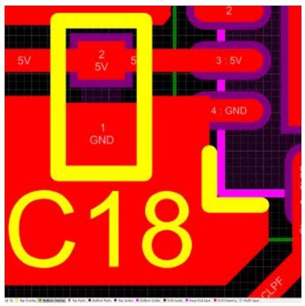
Let’s first understand what decoupling capacitors are. There are usually 0.1uF, and sometimes 2.2nF capacitors that are placed between the supply rails and ground to help prevent the transmission of noise through the power lines in the circuit. As seen in the picture below, the capacitor C18 is a decoupling capacitor for the IC to prevent noise from entering into its 5V input.
Decoupling caps are also used at the input and output stages of on-board power supplies. These capacitors reduce the noise coming from the rest of the circuit, usually from switching components and harmonics getting into sensitive ICs power rails.
These caps can sometimes cause unintended issues. Ceramic caps have a tendency to fail short and what happens if a decoupling cap fails short? It will short Vcc and GND! This is what you see in the picture below – a burned out cap that was used at the input stage of a power supply. During operation, it failed short and burned out until it vaporised into smoke!

How can we design for higher reliability – to avoid such an issue? Here are a few things to keep in mind.
1. Choose a good supplier for these caps and periodically test the parts coming through your supply chain before installing in products.
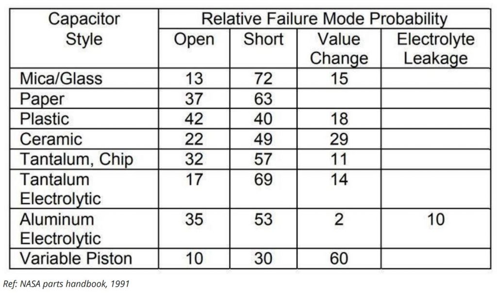
2. You could use polyester or polystyrene based capacitors which have a higher probability to fail open. Below, you can see a table outlining the failure modes of common capacitors. Note that this data is from NASA in 1991, so you should use these numbers only as a reference for comparison between types of caps, not as absolute values for your reliability calculations.
3. Use two series capacitors. With this method, your overall capacitance will decrease, hence you might have to use larger value caps in series, but the probability of failing short between Vcc and GND reduces – since if one fails, the other capacitor is still protecting a direct short.
Using the above three methods, you can reduce the chances of product failures in the field involving high power circuits and ensure that the products you ship have reliable decoupling.
is there a course available to learn everything about batteries and BMS when I come from a non science background and is someone who wants to learn these things to start a business about lithium batteries.